
【前回】GCPサイト間VPNの構築(4.Ciscoルーターの設定)
【次回】GCPサイト間VPNの構築(6.gcloud CLI によるVPN接続の作成)
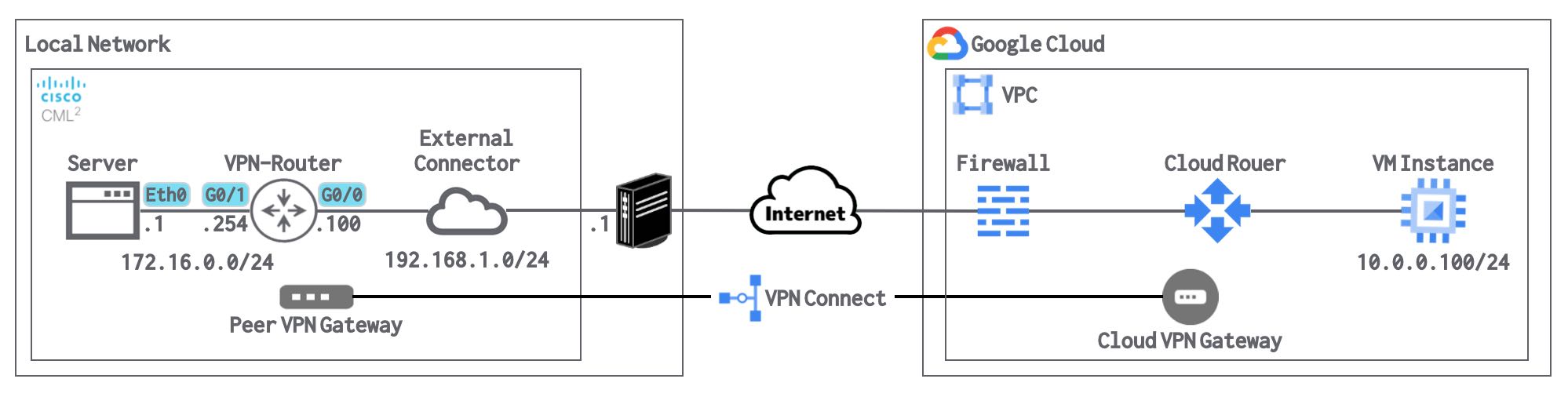
ネットワーク構成
下記のネットワーク構成で、オンプレ環境に見立てたCML上のLAN(172.16.0.0/24)とGCP上のサブネット(10.0.0.0/24)が直接通信できるようにします。※Server(172.16.0.1)とVMインスタンス(10.0.0.100)で、Pingによる疎通確認ができるようにしていきます。
ステータス確認
CiscoルーターとGCPのステータス確認を実施します。
Ciscoルーターのステータス確認
Ciscoルーターのステータスを確認します。
トンネルインターフェースがリンクアップしていることを確認します。
show ip interface briefVPN-Router#show ip interface brief
Interface IP-Address OK? Method Status Protocol
GigabitEthernet0/0 192.168.1.100 YES manual up up
GigabitEthernet0/1 172.16.0.254 YES manual up up
GigabitEthernet0/2 unassigned YES unset administratively down down
GigabitEthernet0/3 unassigned YES unset administratively down down
NVI0 192.168.1.100 YES unset up up
Tunnel1 169.254.0.2 YES manual up upIKEv2のステータスを確認します。
show crypto ikev2 saVPN-Router#show crypto ikev2 sa
IPv4 Crypto IKEv2 SA
Tunnel-id Local Remote fvrf/ivrf Status
1 192.168.1.100/4500 XXX.XXX.XXX.XXX/4500 none/none READY
Encr: AES-CBC, keysize: 128, PRF: SHA256, Hash: SHA256, DH Grp:16, Auth sign: PSK, Auth verify: PSK
Life/Active Time: 86400/296 sec
IPv6 Crypto IKEv2 SAStatusが「READY」となっていれば、IKEv2は確立されています。
IPSecのステータスを確認します。
show crypto ipsec saVPN-Router#show crypto ipsec sa
interface: Tunnel1
Crypto map tag: Tunnel1-head-0, local addr 192.168.1.100
protected vrf: (none)
local ident (addr/mask/prot/port): (0.0.0.0/0.0.0.0/0/0)
remote ident (addr/mask/prot/port): (0.0.0.0/0.0.0.0/0/0)
current_peer XXX.XXX.XXX.XXX port 4500
PERMIT, flags={origin_is_acl,}
#pkts encaps: 11, #pkts encrypt: 11, #pkts digest: 11
#pkts decaps: 11, #pkts decrypt: 11, #pkts verify: 11
#pkts compressed: 0, #pkts decompressed: 0
#pkts not compressed: 0, #pkts compr. failed: 0
#pkts not decompressed: 0, #pkts decompress failed: 0
#send errors 0, #recv errors 0
local crypto endpt.: 192.168.1.100, remote crypto endpt.: XXX.XXX.XXX.XXX
plaintext mtu 1422, path mtu 1500, ip mtu 1500, ip mtu idb GigabitEthernet0/0
current outbound spi: 0x3F65BF5A(1063632730)
PFS (Y/N): N, DH group: none
inbound esp sas:
spi: 0x53A1A185(1403101573)
transform: esp-256-aes esp-sha256-hmac ,
in use settings ={Tunnel UDP-Encaps, }
conn id: 24, flow_id: SW:24, sibling_flags 80000040, crypto map: Tunnel1-head-0
sa timing: remaining key lifetime (k/sec): (4370907/3559)
IV size: 16 bytes
replay detection support: Y
Status: ACTIVE(ACTIVE)
inbound ah sas:
inbound pcp sas:
outbound esp sas:
spi: 0x3F65BF5A(1063632730)
transform: esp-256-aes esp-sha256-hmac ,
in use settings ={Tunnel UDP-Encaps, }
conn id: 23, flow_id: SW:23, sibling_flags 80000040, crypto map: Tunnel1-head-0
sa timing: remaining key lifetime (k/sec): (4370907/3559)
IV size: 16 bytes
replay detection support: Y
Status: ACTIVE(ACTIVE)
outbound ah sas:
outbound pcp sas:「pkts encrypt」と「pkts decrypt」の数値がカウントされていれば、暗号化通信が行われています。
BGPのステータスを確認します。
show ip bgp summaryVPN-Router#show ip bgp summary
BGP router identifier 172.16.0.254, local AS number 65001
BGP table version is 3, main routing table version 3
2 network entries using 288 bytes of memory
2 path entries using 168 bytes of memory
2/2 BGP path/bestpath attribute entries using 320 bytes of memory
1 BGP AS-PATH entries using 24 bytes of memory
0 BGP route-map cache entries using 0 bytes of memory
0 BGP filter-list cache entries using 0 bytes of memory
BGP using 800 total bytes of memory
BGP activity 2/0 prefixes, 2/0 paths, scan interval 60 secs
Neighbor V AS MsgRcvd MsgSent TblVer InQ OutQ Up/Down State/PfxRcd
169.254.0.1 4 65000 19 21 3 0 0 00:05:19 1
「State/PfxRcd」の値が数値となっていれば、BGPネイバーが確立され、ルート情報を受け取っています。
ルーティングのステータスを確認します。
show ip routeVPN-Router#show ip route
Codes: L - local, C - connected, S - static, R - RIP, M - mobile, B - BGP
D - EIGRP, EX - EIGRP external, O - OSPF, IA - OSPF inter area
N1 - OSPF NSSA external type 1, N2 - OSPF NSSA external type 2
E1 - OSPF external type 1, E2 - OSPF external type 2
i - IS-IS, su - IS-IS summary, L1 - IS-IS level-1, L2 - IS-IS level-2
ia - IS-IS inter area, * - candidate default, U - per-user static route
o - ODR, P - periodic downloaded static route, H - NHRP, l - LISP
a - application route
+ - replicated route, % - next hop override, p - overrides from PfR
Gateway of last resort is 192.168.1.1 to network 0.0.0.0
S* 0.0.0.0/0 [1/0] via 192.168.1.1
10.0.0.0/24 is subnetted, 1 subnets
B 10.0.0.0 [20/100] via 169.254.0.1, 00:05:03
169.254.0.0/16 is variably subnetted, 2 subnets, 2 masks
C 169.254.0.0/30 is directly connected, Tunnel1
L 169.254.0.2/32 is directly connected, Tunnel1
172.16.0.0/16 is variably subnetted, 2 subnets, 2 masks
C 172.16.0.0/24 is directly connected, GigabitEthernet0/1
L 172.16.0.254/32 is directly connected, GigabitEthernet0/1
192.168.1.0/24 is variably subnetted, 2 subnets, 2 masks
C 192.168.1.0/24 is directly connected, GigabitEthernet0/0
L 192.168.1.100/32 is directly connected, GigabitEthernet0/0「10.0.0.0/24」のルートをBGPで受け取っていることを確認します。
GCPのステータス確認
GCPのコンソール画面上で、「CLOUD VPNトンネル」のステータスを確認します。

VPNトンネルとBGPのステータスが以下の通りとなっていることを確認します。
・VPNトンネルのステータス:確立済み
・BGPセッションのステータス:BGPが確立されました
疎通確認
CML上のServerとGCP上のVMインスタンス間で疎通確認を実施します。
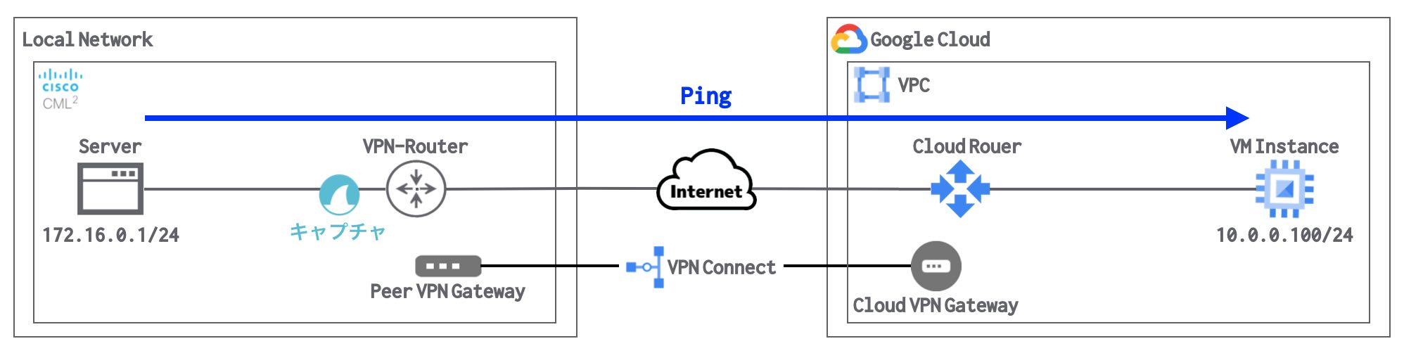
Server → VMインスタンス の疎通確認
CML上のServerからGCP上のVMインスタンスへPing(ICMP)を実施します。
ping 10.0.0.100cisco@Server:~$ ping 10.0.0.100
PING 10.0.0.100 (10.0.0.100): 56 data bytes
64 bytes from 10.0.0.100: seq=0 ttl=62 time=18.508 ms
64 bytes from 10.0.0.100: seq=1 ttl=62 time=17.783 ms
64 bytes from 10.0.0.100: seq=2 ttl=62 time=18.943 ms
64 bytes from 10.0.0.100: seq=3 ttl=62 time=13.076 ms
64 bytes from 10.0.0.100: seq=4 ttl=62 time=22.980 ms
^C
--- 10.0.0.100 ping statistics ---
5 packets transmitted, 5 packets received, 0% packet loss
round-trip min/avg/max = 13.076/18.258/22.980 msCML上のServerからGCP上のVMインスタンスへPing(ICMP)による疎通が可能なことを確認します。
VMインスタンス → Server の疎通確認
GCP上のVMインスタンスからCML上のServerへPing(ICMP)を実施します。
ping 172.16.0.1vm-gcp-vpn-test-001:~$ ping 172.16.0.1
PING 172.16.0.1 (172.16.0.1) 56(84) bytes of data.
64 bytes from 172.16.0.1: icmp_seq=1 ttl=62 time=21.0 ms
64 bytes from 172.16.0.1: icmp_seq=2 ttl=62 time=12.5 ms
64 bytes from 172.16.0.1: icmp_seq=3 ttl=62 time=13.8 ms
64 bytes from 172.16.0.1: icmp_seq=4 ttl=62 time=12.0 ms
64 bytes from 172.16.0.1: icmp_seq=5 ttl=62 time=96.1 ms
^C
--- 172.16.0.1 ping statistics ---
5 packets transmitted, 5 received, 0% packet loss, time 10ms
rtt min/avg/max/mdev = 12.009/31.081/96.103/32.670 msGCP上のVMインスタンスからCML上のServerへPing(ICMP)による疎通が可能なことを確認します。
暗号化の確認(パケットキャプチャの確認)
VPN-Routerの通過前後でパケットキャプチャを行い、暗号化と復号を確認します。
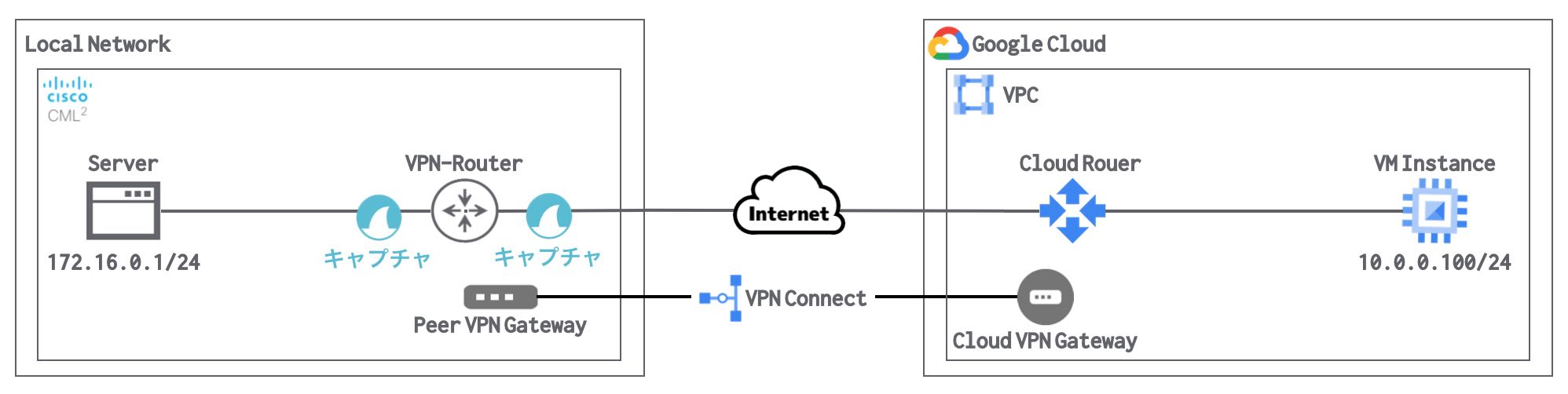
Server → VMインスタンス のパケットキャプチャ
ServerとVPN-Router間のパケットを確認します。

通信が暗号化されていないことが分かります。
VPN-RouterとInternet間のパケットを確認します。

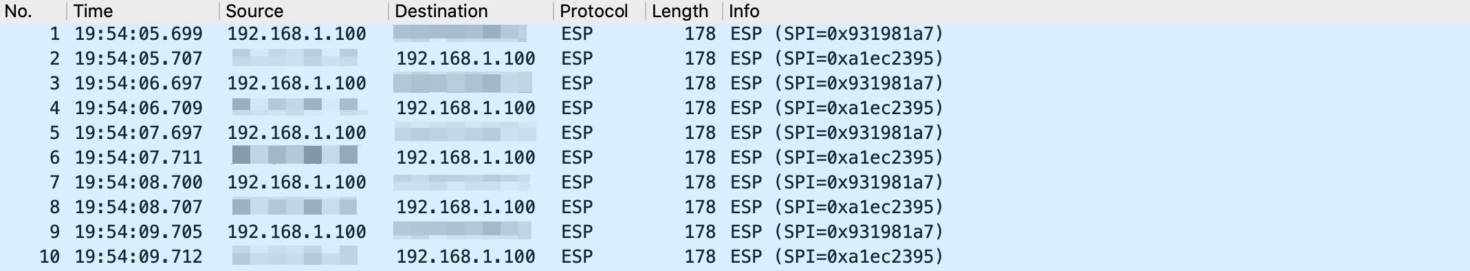
通信が暗号化されていることが分かります。
VMインスタンス → Server のパケットキャプチャ
InternetとVPN-Router間のパケットを確認します。

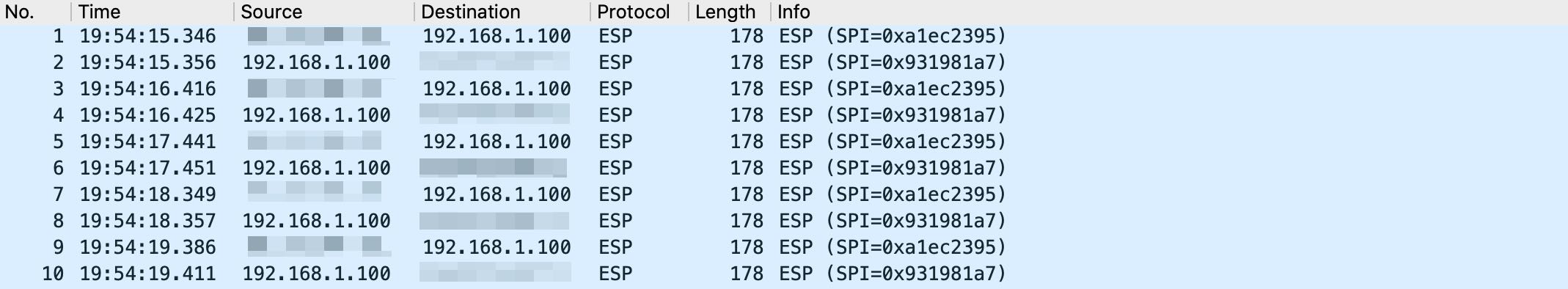
通信が暗号化されていることが分かります。
VPN-RouterとServer間のパケットを確認します。

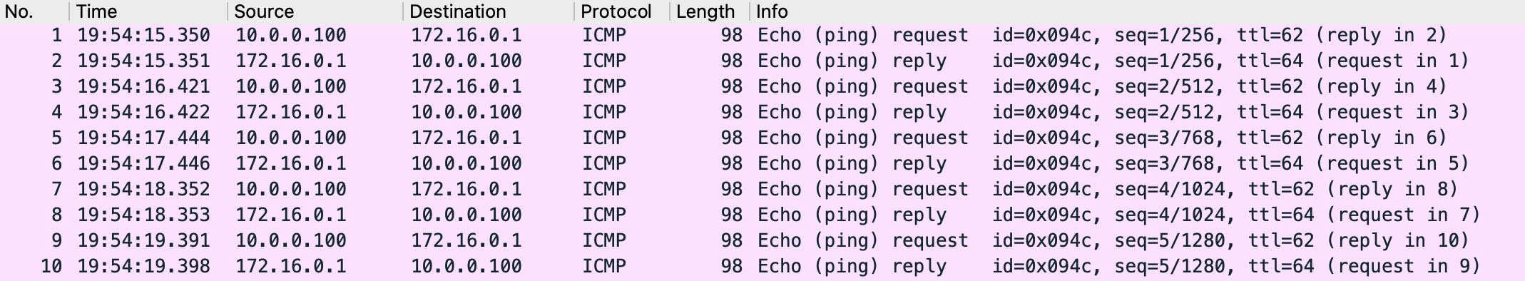
暗号化されていた通信が復号されていることが分かります。
以上で、GCPサイト間VPNの構築(5.ステータス確認・疎通確認)の説明は完了です!
【前回】GCPサイト間VPNの構築(4.Ciscoルーターの設定)
【次回】GCPサイト間VPNの構築(6.gcloud CLI によるVPN接続の作成)