ネットワークのトラブルとして多く発生する『L2ループ』について、CMLで環境を構築し説明します。
ネットワーク構成
ネットワーク環境構築
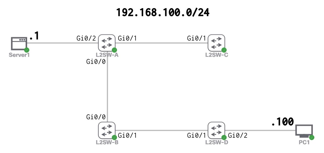
CMLで下記の環境を構築します。全スイッチでSTPの設定を削除します。
hostname L2SW-A

no spanning-tree vlan 1hostname L2SW-B
no spanning-tree vlan 1hostname L2SW-C
no spanning-tree vlan 1hostname L2SW-D
no spanning-tree vlan 1hostname Server1
ifconfig eth0 192.168.100.1 netmask 255.255.255.0 up
route add -net 0.0.0.0/0 dev eth0hostname PC1
ifconfig eth0 192.168.100.100 netmask 255.255.255.0 up
route add -net 0.0.0.0/0 dev eth0疎通確認
Server1とPC1の間でPingを実施し、疎通可能であることを確認します。RTTの平均は、約16ミリ秒です。
ping 192.168.100.100cisco@Server1:~$ ping 192.168.100.100
PING 192.168.100.100 (192.168.100.100): 56 data bytes
64 bytes from 192.168.100.100: seq=0 ttl=64 time=18.152 ms
64 bytes from 192.168.100.100: seq=1 ttl=64 time=18.817 ms
64 bytes from 192.168.100.100: seq=2 ttl=64 time=10.893 ms
64 bytes from 192.168.100.100: seq=3 ttl=64 time=17.242 ms
64 bytes from 192.168.100.100: seq=4 ttl=64 time=15.718 ms
^C
--- 192.168.100.100 ping statistics ---
5 packets transmitted, 5 packets received, 0% packet loss
round-trip min/avg/max = 10.893/16.164/18.817 msping 192.168.100.1PC1:~$ ping 192.168.100.1
PING 192.168.100.1 (192.168.100.1): 56 data bytes
64 bytes from 192.168.100.1: seq=0 ttl=42 time=16.777 ms
64 bytes from 192.168.100.1: seq=1 ttl=42 time=14.935 ms
64 bytes from 192.168.100.1: seq=2 ttl=42 time=18.924 ms
64 bytes from 192.168.100.1: seq=3 ttl=42 time=18.915 ms
64 bytes from 192.168.100.1: seq=4 ttl=42 time=14.018 ms
^C
--- 192.168.100.1 ping statistics ---
5 packets transmitted, 5 packets received, 0% packet loss
round-trip min/avg/max = 14.018/16.713/18.924 msMACアドレステーブルの確認
L2SW-AでPC1のMACアドレスの登録状況を確認します。PC1のMACアドレスは、”5254.0015.6ED9″で、L2SW-AではGi0/0(L2SW-Bとの接続ポート)から学習しています。
ifconfigPC1:~$ ifconfig
eth0 Link encap:Ethernet HWaddr 52:54:00:15:6E:D9
inet addr:192.168.100.100 Bcast:192.168.100.255 Mask:255.255.255.0show mac address-table | inc 5254.0015.6ed9L2SW-A#show mac address-table | inc 5254.0015.6ed9
1 5254.0015.6ed9 DYNAMIC Gi0/0L2ループ構成
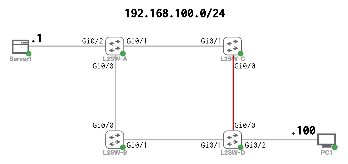
L2ループ構成への変更
L2ループ構成を作るため、L2SW-CとL2SW-Dを接続します。
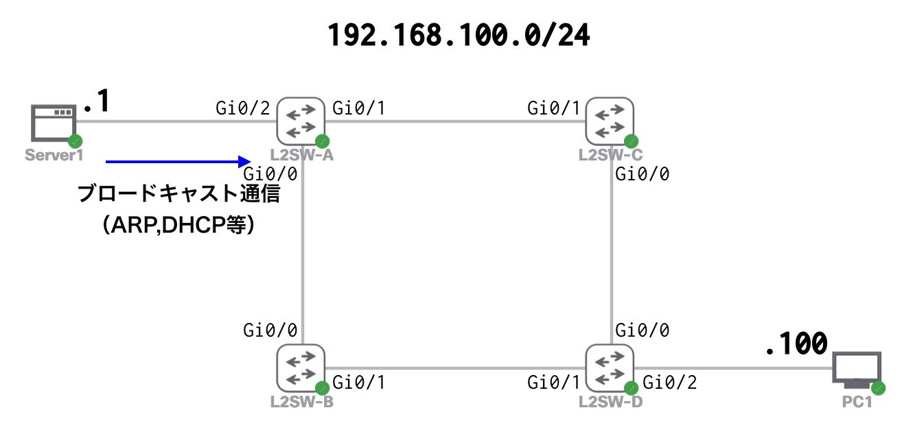
L2ループ発生のメカニズム
Server1からブロードキャスト通信が発生
Server1から、ARP等のブロードキャスト通信が発生します。
同一セグメント内の通信についての詳細は、下記を参照してください。
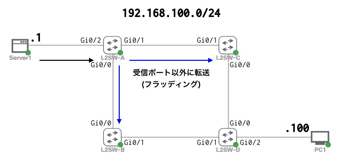
L2SW-Aがフラッディング
L2SW-Aが受信ポート以外に転送します。(フラッディング)
L2SW-BとL2SW-Cがフラッディング
L2SW-BとL2SW-Cが受信ポート以外に転送します。(フラッディング)
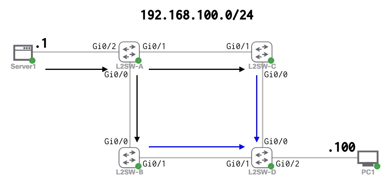
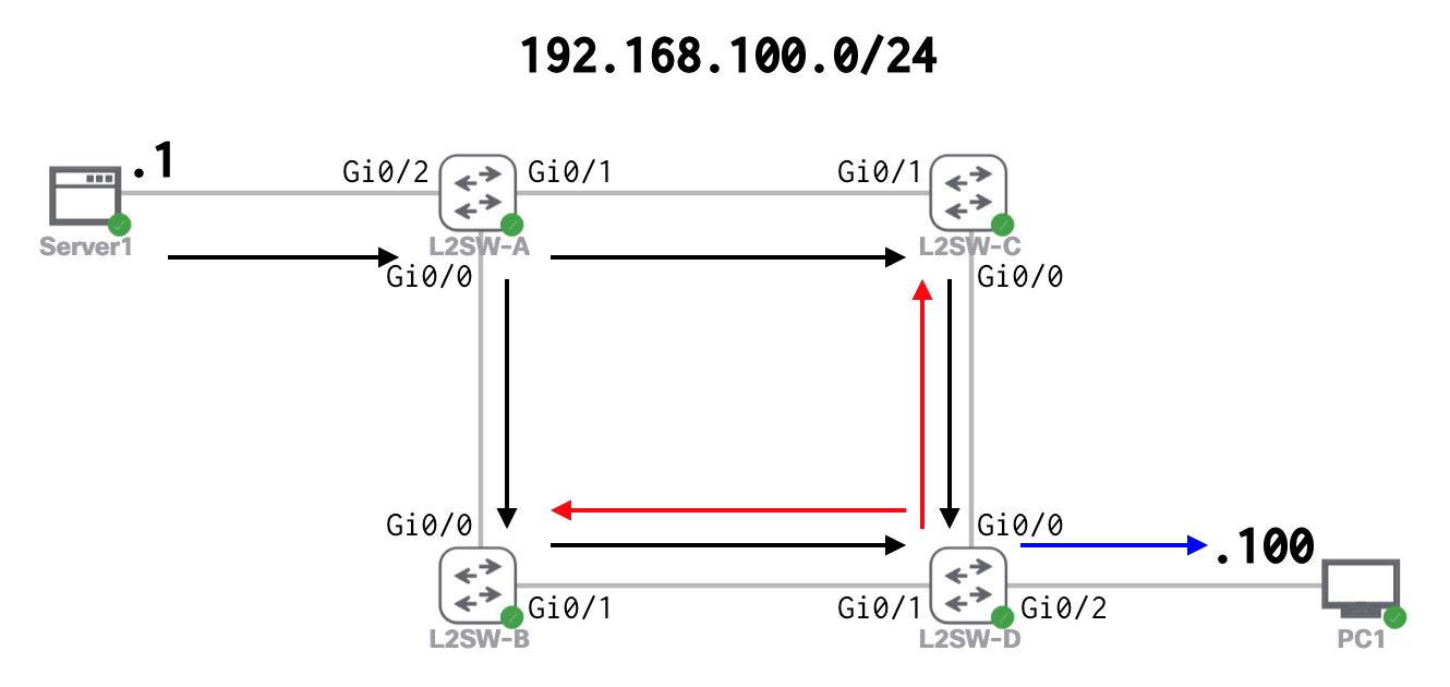
L2SW-Dがフラッディング
L2SW-Dが受信ポート以外に転送します。(フラッディング)
この時、L2SW-Bから受け取ったパケットはL2SW-Cへ、L2SW-Cから受け取ったパケットはL2SW-Bへ、それぞれ転送してしまいます。(赤矢印)
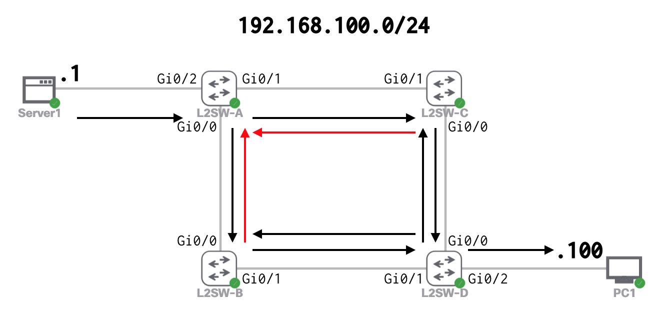
更にL2SW-BとL2SW-Cがフラッディング
L2SW-BとL2SW-Cが、L2SW-Dから受け取ったパケットを、受信ポート以外に転送します。(フラッディング)
L2ループによるブロードキャストストームの完成
全スイッチがフラッディングを繰り返すことにより、ネットワーク内にブロードキャスト通信が流れ続けます。(この状態をブロードキャストストームと言います。)
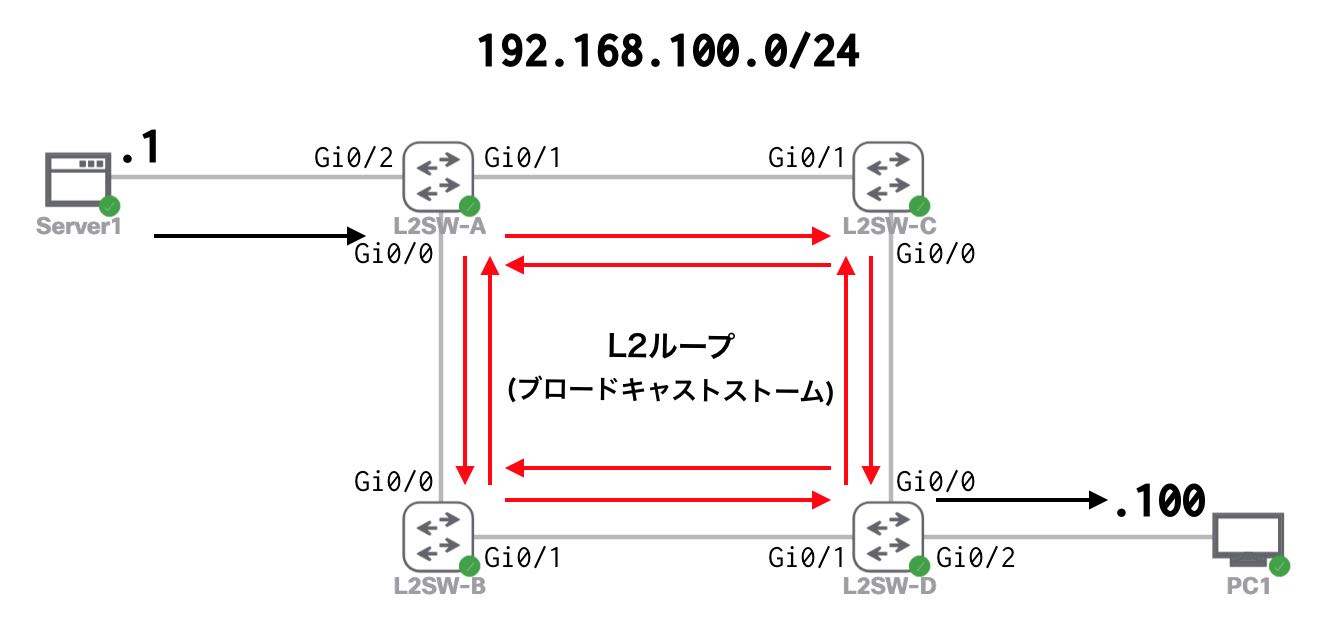
これにより、全スイッチの処理負荷が高くなり、ネットワーク全体がダウンしてしまいます。
L2ループによる通信影響の確認
CML上でL2ループ状態にした時の通信状況を確認します。
Server1とPC1の間の通信状況
Server1とPC1の間のPingは、パケットロスが頻発したり、RTTが大きくなります。
ping 192.168.100.100cisco@Server1:~$ ping 192.168.100.100
PING 192.168.100.100 (192.168.100.100): 56 data bytes
64 bytes from 192.168.100.100: seq=2 ttl=64 time=1022.310 ms
64 bytes from 192.168.100.100: seq=3 ttl=64 time=1036.276 ms
64 bytes from 192.168.100.100: seq=4 ttl=64 time=42.930 ms
64 bytes from 192.168.100.100: seq=5 ttl=64 time=1019.086 ms
64 bytes from 192.168.100.100: seq=6 ttl=64 time=1038.932 ms
64 bytes from 192.168.100.100: seq=7 ttl=64 time=2022.025 ms
64 bytes from 192.168.100.100: seq=8 ttl=64 time=2012.244 ms
64 bytes from 192.168.100.100: seq=9 ttl=64 time=2018.166 ms
64 bytes from 192.168.100.100: seq=10 ttl=64 time=2027.724 ms
64 bytes from 192.168.100.100: seq=11 ttl=64 time=1034.307 ms
64 bytes from 192.168.100.100: seq=12 ttl=64 time=1016.383 ms
64 bytes from 192.168.100.100: seq=13 ttl=64 time=2019.396 ms
64 bytes from 192.168.100.100: seq=14 ttl=64 time=3035.793 ms
64 bytes from 192.168.100.100: seq=15 ttl=64 time=3027.524 ms
64 bytes from 192.168.100.100: seq=17 ttl=64 time=2011.451 ms
64 bytes from 192.168.100.100: seq=16 ttl=64 time=3017.294 ms
^C
--- 192.168.100.100 ping statistics ---
20 packets transmitted, 16 packets received, 20% packet loss
round-trip min/avg/max = 42.930/1712.615/3035.793 msping 192.168.100.1PC1:~$ ping 192.168.100.1
PING 192.168.100.1 (192.168.100.1): 56 data bytes
64 bytes from 192.168.100.1: seq=1 ttl=42 time=2011.632 ms
64 bytes from 192.168.100.1: seq=2 ttl=42 time=1019.904 ms
64 bytes from 192.168.100.1: seq=0 ttl=42 time=3026.496 ms
64 bytes from 192.168.100.1: seq=3 ttl=42 time=1013.259 ms
64 bytes from 192.168.100.1: seq=4 ttl=42 time=1009.005 ms
64 bytes from 192.168.100.1: seq=5 ttl=42 time=2055.180 ms
64 bytes from 192.168.100.1: seq=7 ttl=42 time=2011.311 ms
64 bytes from 192.168.100.1: seq=6 ttl=42 time=3031.865 ms
64 bytes from 192.168.100.1: seq=8 ttl=42 time=1031.989 ms
64 bytes from 192.168.100.1: seq=9 ttl=42 time=1014.458 ms
64 bytes from 192.168.100.1: seq=11 ttl=42 time=1026.061 ms
64 bytes from 192.168.100.1: seq=14 ttl=42 time=2008.766 ms
64 bytes from 192.168.100.1: seq=10 ttl=42 time=6017.121 ms
64 bytes from 192.168.100.1: seq=12 ttl=42 time=4019.008 ms
64 bytes from 192.168.100.1: seq=13 ttl=42 time=3022.237 ms
64 bytes from 192.168.100.1: seq=15 ttl=42 time=2010.950 ms
^C
--- 192.168.100.1 ping statistics ---
19 packets transmitted, 16 packets received, 15% packet loss
round-trip min/avg/max = 1009.005/2208.077/6017.121 msパケットキャプチャの確認
L2ループ状態でネットワーク内に流れているパケットをキャプチャすると、ARP通信やDHCP等のブロードキャスト通信が多く流れていることが分かります。

MACアドレステーブルの確認
L2SW-AでPC1のMACアドレスの登録状況を確認すると、Gi0/0(L2SW-Bとの接続ポート)とGi0/1(L2SW-Cとの接続ポート)での学習を繰り返していることが分かります。
show mac address-table | inc 5254.0015.6ed9L2SW-A#show mac address-table | inc 5254.0015.6ed9
1 5254.0015.6ed9 DYNAMIC Gi0/0
L2SW-A#show mac address-table | inc 5254.0015.6ed9
1 5254.0015.6ed9 DYNAMIC Gi0/1
L2SW-A#show mac address-table | inc 5254.0015.6ed9
1 5254.0015.6ed9 DYNAMIC Gi0/1
L2SW-A#show mac address-table | inc 5254.0015.6ed9
1 5254.0015.6ed9 DYNAMIC Gi0/0実際のネットワーク機器では一つのMACアドレスを複数ポートから学習すると下記のようなログが出力されます。このログが出力された場合、L2ループが発生してる確率が高いです。
%SW_MATM-4-MACFLAP_NOTIF: Host XXXX.XXXX.XXXX in vlan 1 is flapping between port Gi0/XX and port Gi0/XXスイッチのCPU状態
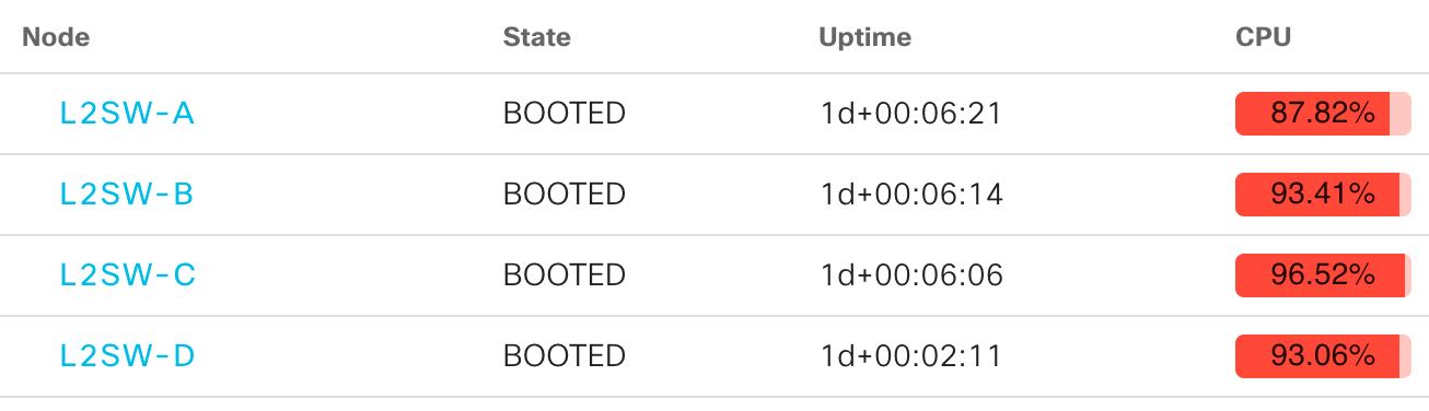
通常状態のCPU利用率は30%前後となっています。

L2ループ状態時は90%前後となっています。※CML上では90%前後ですが、実際のネットワーク環境では100%に張り付くことも珍しくありません。
CML上では、ネットワーク全体のダウンには至りませんでしたが、実際のネットワークでL2ループが発生すると、ネットワーク機器のCPUが100%に張り付き、機器自体がダウンすることもありえます。
ネットワークの冗長性を維持しながら、L2ループを防ぐための仕組みとして、STPやFlexLinkという技術があります。
以上で、L2ループによるネットワークダウン(発生メカニズムの説明)の説明は完了です!